
One of the most recognisable layout designs most UK modellers are familiar with is Cyril Freezers ‘Minories’ layout. An inner London terminus based on the Metropolitan Line at Liverpool Street it is a very simple and effective design giving lots of potential for intense operation. The design was based on two crossovers using contemporary (1960’s) ready to lay track. The Minories design would work just as well with many other prototypes, and I wanted to see if I could adapt it to get a similar inner city feel with a Southern Region emphasis. The original layout plan and this one works particularly well for Multiple Unit stock, be that DMU or EMU, and with releases of good quality Southern EMU models from Bachmann and Hornby, this seemed a good opportunity to design Manitoba Quays. Paul Lunn and I worked from my track plan to a three dimensional mock up of this urban branch line terminus, and this is how it went..

What’s the Canadian Province of Manitoba got to do with Southern Region stations eh? Well the idea behind this project was to retain the original Minories inner London, feeling of being in a cutting, urban, hemmed in and making the best use of restricted and expensive inner city real estate. Part of the idea is to give some plausibility to the scheme and here we indulge in a little make believe and tweeks of history to develop a storyline for the stations development. The big thing to emphasise here is that this design isn’t specifically south London. Like the Minories design this could be just as easily set in Birmingham, Glasgow, Newcastle, Bradford, anywhere really where you can envisage that there was a suburban terminus with an intense service. The actual design fits multiple unit shuttle operations slightly better than locomotive hauled, particularly with the concept being to try and keep this in a small format, the footprint being 6ft x 2ft. With the advent of TT120, and looking at N fine scale this same design in this footprint would really come alive. Going up a scale taking a Iain Futers approach could see this as a truncated route. Scottish Parcels with Dapols 08, Heljan 24/25/27/27 working short but plausible BR green to blue era trains….

The Back Story
The second half of the 19th century saw London’s dock system double in size. The port’s rapid and linear growth as the world’s main trade centre resulted inupgrading and re-building of existing docks and the construction of new facilities such as the Canada Dock, completed in the 1870’s. This area of docks was located on the southern side of the River Thames roughly one mile east of Tower Bridge. The name Canada Docks was given to the area as that’s where large amounts of shipping, both import and export to Canada took place. For this plan we’ve assumed that the dock and commercial area around Rotherhithe was busy generating substantial commuting traffic in and out of the area. In reality of course the increasing use of containers in shipping lead to a rapid decline of trade in these traditional dockland areas across the country, not just London.The branch is an intensively worked short stub with the junction in the region of the South Bermondsey station. The line routed almost due north for about a mile to reach the Terminus at Manitoba Quays. At this station we’ve assumed there was also a link to the northbank of the Thames following the alignment of the Rotherhithe road tunnel, allowing Southern Region access into a terminus in the Poplar area, and connections to freight at the top of the Isle of Dogs. This route, rather like the ‘widened lines’ at Kings Cross, branches off from the station throat and in the viewing arrangement ducks under a road way and disappears almost immediately as the traffic comes on scene. The primary traffic through the station throat into Manitoba Quays comes from the east-west route of the old London Brighton and South Coast Railway (LBSCR), and South East and Chatham (SECR) routes, this being a joint branch from London Bridge station connecting through South Bermondsey. The connection into London Bridge also allows access to suburban and electrified lines to and from Waterloo, the trains routing via Clapham Junction, Peckham to South Bermondsey. This might have given the London and South Western Railway closer access to the City of London. At the foreground of the layout is another single line passenger branch, but parcels could also utilise this to add operational interest, this would be SECR origin. The route follows the eastern River Thames toWoolwich and Gravesend, allowing entry to Manitoba Quay without reversal at London Bridge. The Junction for this branch is around Greenwich Market, keeping the route closer to the south bank of the River Thames through North Deptford and the Surrey Docks.
Train Service and Operations
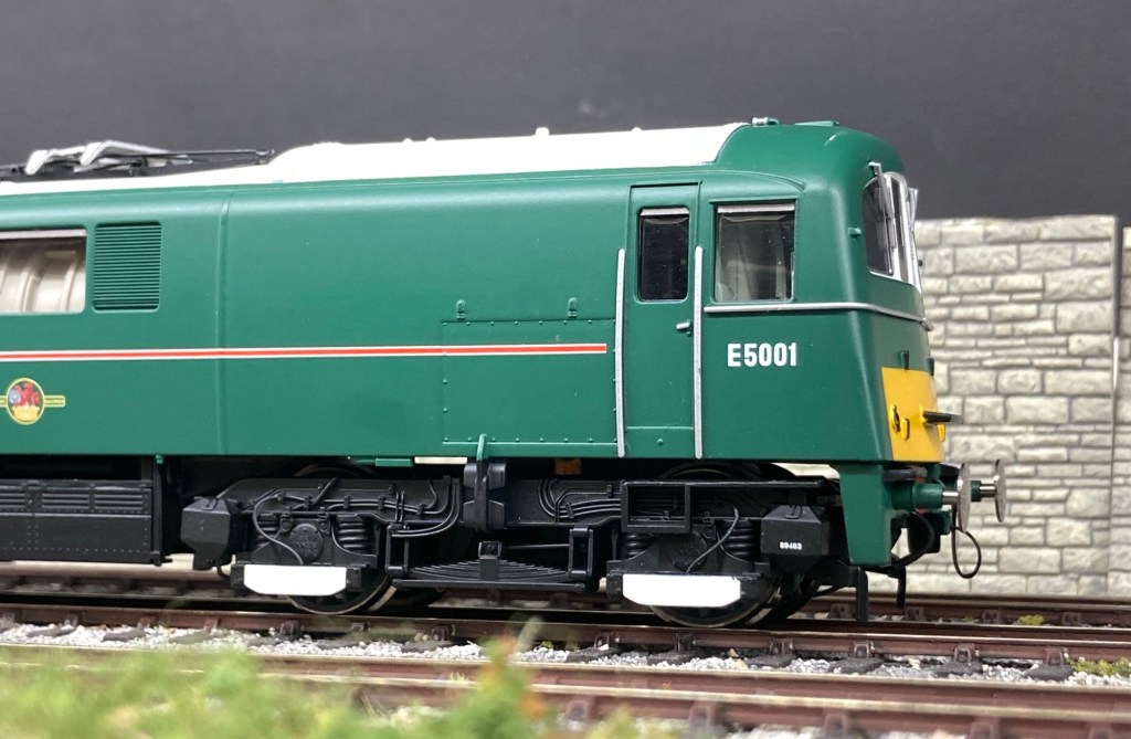
One feature of the southern electric lines was the intensity of the service. Adopting electric units meant that efficiencies in operation were achieved without the expense of additional locomotives and time delays of running round trains. This layout design allows that intensity of service to be replicated at a terminus in a compact space, the baseboard footprint being 6ft x 24ft. So, with this design being in 4mm scale, let’s look at the stock that’s available. Bachmann and Hornby provide suitable ready to run Southern Region electric units. All track on the layout is anticipated to be built as third rail electrified. One benefit of history is that a good number of prototypical units ran in two car formations. With the relatively short layout we are proposed this means a two car unit looks realistic, and allows further operational potential with splitting a four car train into two, two car units. The era I’ve chosen is the late 1950’s into the early 1960’s as that gives us the most variety in using available RTR units. It will also allow the use of Steam locomotives too on parcels, engineering and freight trains. Cross Thames freight can be depicted using class 73 electro diesels, the Hornby Class 71 a potential candidate too.

For the EMU’s
Bachmann 2-EPB British Rail 2 car design introduced in the mid 1950’s, suitable for the London Bridge services, Isle of Dogs and the Greenwich branch. Run in pairs to allow longer formations and splitting of trains.
Bachmann 4CEP British Rail 4 car design introduced late 50’s for Kent coast electrification. For use as longer distance express commuter service. The 4BEP could also be considered, and recent releases of Bachmann’s refurbished 4CEP could bring the design into the 90’s.
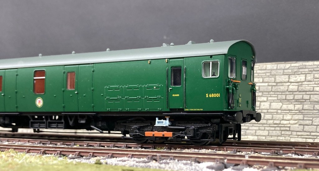
Bachmann MLV Parcels EMU

Hornby 2-Bil Southern Railway design, built mid to late 1930’s and use as per the 2-EPB.

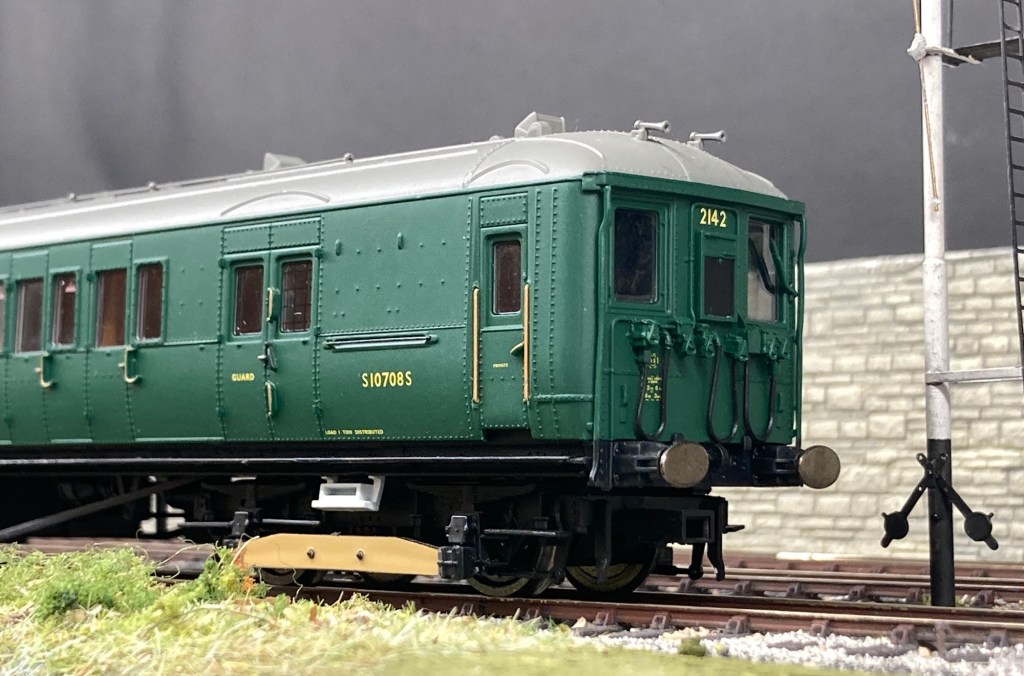
Hornby 2-Hal Southern Railway design built mid to late 1930’s but primarily to and from London Bridge on the main route to and from the Manitoba Quays.


Hornby 4VEP British Rail design 4 car set introduced in 1967. For this particular project they are introduced slightly too late for me to include them. However for an era including 1967 onward then they could be included into the longer distance express roster.
If there’s space to allow another 40 cms of platform length, then longer distance traffic could be envisaged with the occasional arrival of a 4TC set with a class 33 cutting across via Lambeth and Peckham to Bermondsey.

In terms of Southern Steam outline motive power there is a good range of suitable types that could cover the requirements. I’d suggest that few passenger services are run by steam to keep it plausible. On such a short branch there would have been awkward and time consuming changes for locomotives, the electric multiple units being far more suited to this type of operation. Parcels movements however could take place with steam hauled locomotives providing the motive power.

Useful types would be the Q1, T9 and LSWR 700 class from Hornby, with the N class, C class, E4 from Bachmann adding to the variety.
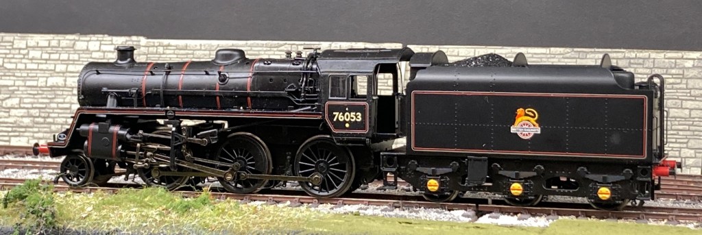
Other types from British Rail would be the Standard class 3MT 2-6-2T and Standard class 4 2-6-4T and 2-6-0 tender types all being seen in the Southern Region London area at the time.

With more length on the platforms, perhaps extending them by an extra foot, Southern Railway operations using exclusively steam power could be run. To help with the movementof stock in the station environment the addition of a station pilot would give more moves. There is nothing to prevent this plan being used for other railway companies or regions.
The Track Plan& Infrastructure

The first thing to mention when looking at the images is that there is no requirement for a double slip. The track plan is designed for, and works correctly with a single slip, but for the mock up phase only having the double slip to hand allowed us to visually capture the flow of the track in three dimensions far better than using a template. I wanted to get a traffic flow that captured the trains snaking across the station throat. My first job was working at Kings Cross, and in lunch breaks and whilst waiting for the train home I often used to watch the trains entering and departing through Gasworks Tunnels, and that was in my mind as I worked out the track plan. I’d chosen the Southern Region for two reasons, we don’t often see urban railways modelled and I could see the benefit of the two car units being a prototypical full length train.

With the layout being fairly short these two car units will look good allowing there still to be a third or double length of platform still visible. This visual element isn’t part of the track plan but more the overall appearance. A four car 4CEP train almost overpowers the station from some angle it looks cramped. With a two car unit this effect is negligible, the space around the empty platform sections giving a more spacious feel to the restricted area, and it visually gives the train more distance to travel. With a prototype that included these two car sets running as multiples there is also the additional opportunity to split, or join a train and send each two car unit out on a different route.
The track chosen was off the shelf OO/HO and the worked example uses Peco Streamline Code 75, their Code 100 is to the same geometry. To get a better appearance I’ve used the large radius points, these also match the single slip. Since this design was formulated Peco have introduced their Code 75 Bullhead track, and this would be worth considering for this plan too. The three way and Y point aren’t yet in the bullhead range, however with careful weathering the existing Code 75 Streamline points could be used without too many issues. The fiddle yard is envisaged to be either a sector plate or cassettes, my preference would be for cassettes allowing units to be turned so that with relatively few units the impression can be given of a different train appearing by swapping a units direction. If I were to build this layout I’ll set it quite high with a track bed height of around 50 inches or so. This will give a natural view point, without it being a helicopter overview and I’d configure it for operating from the front.
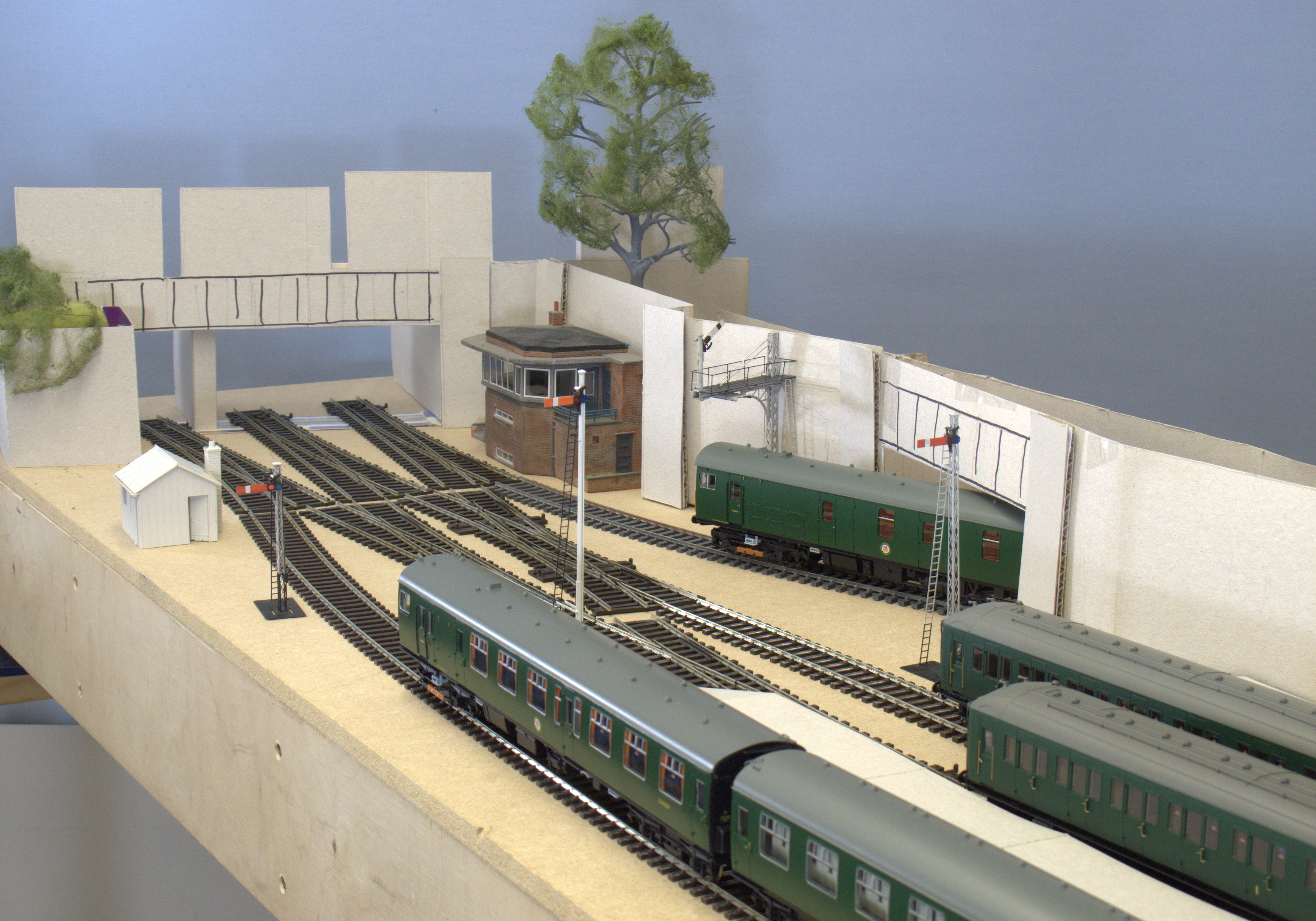
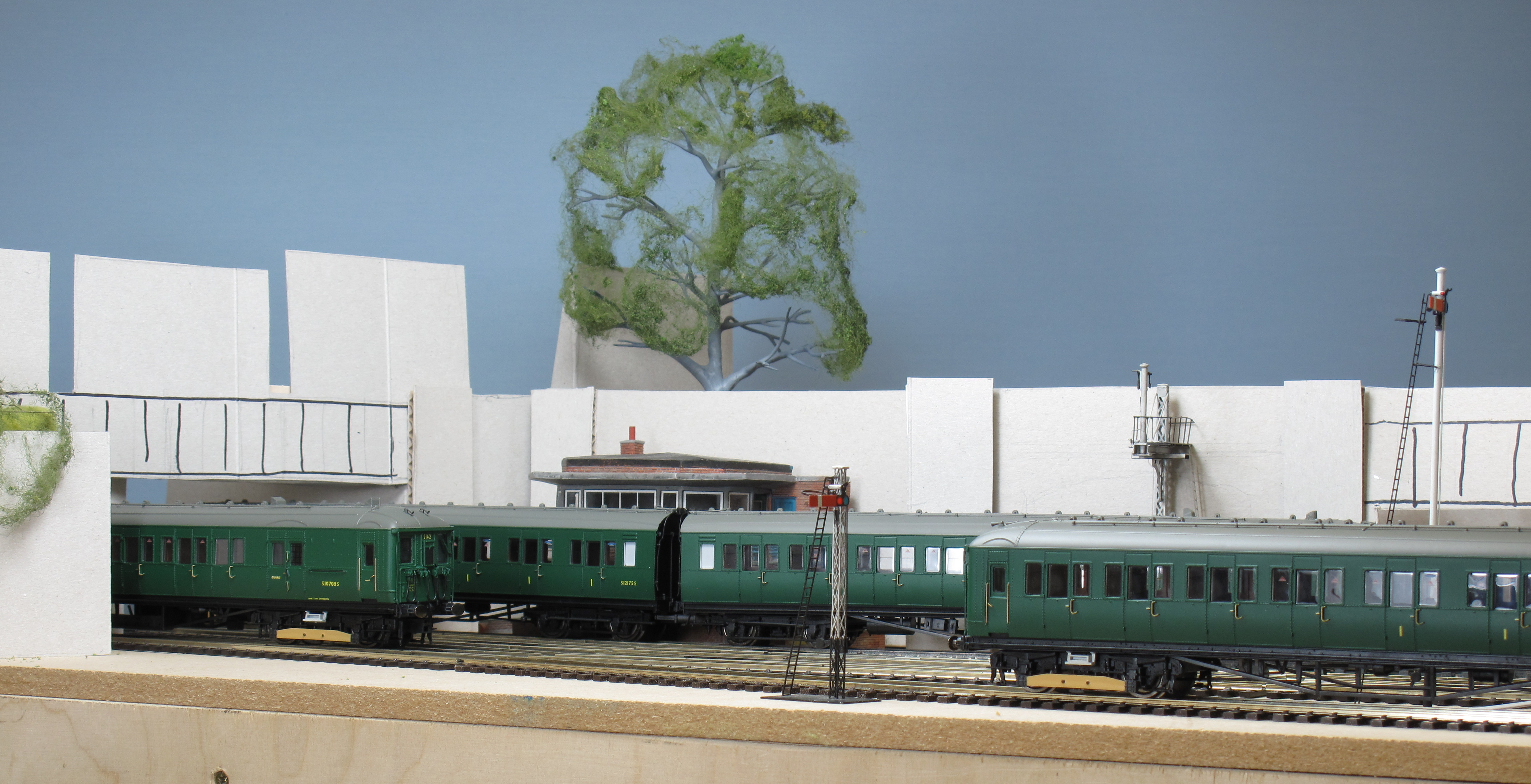
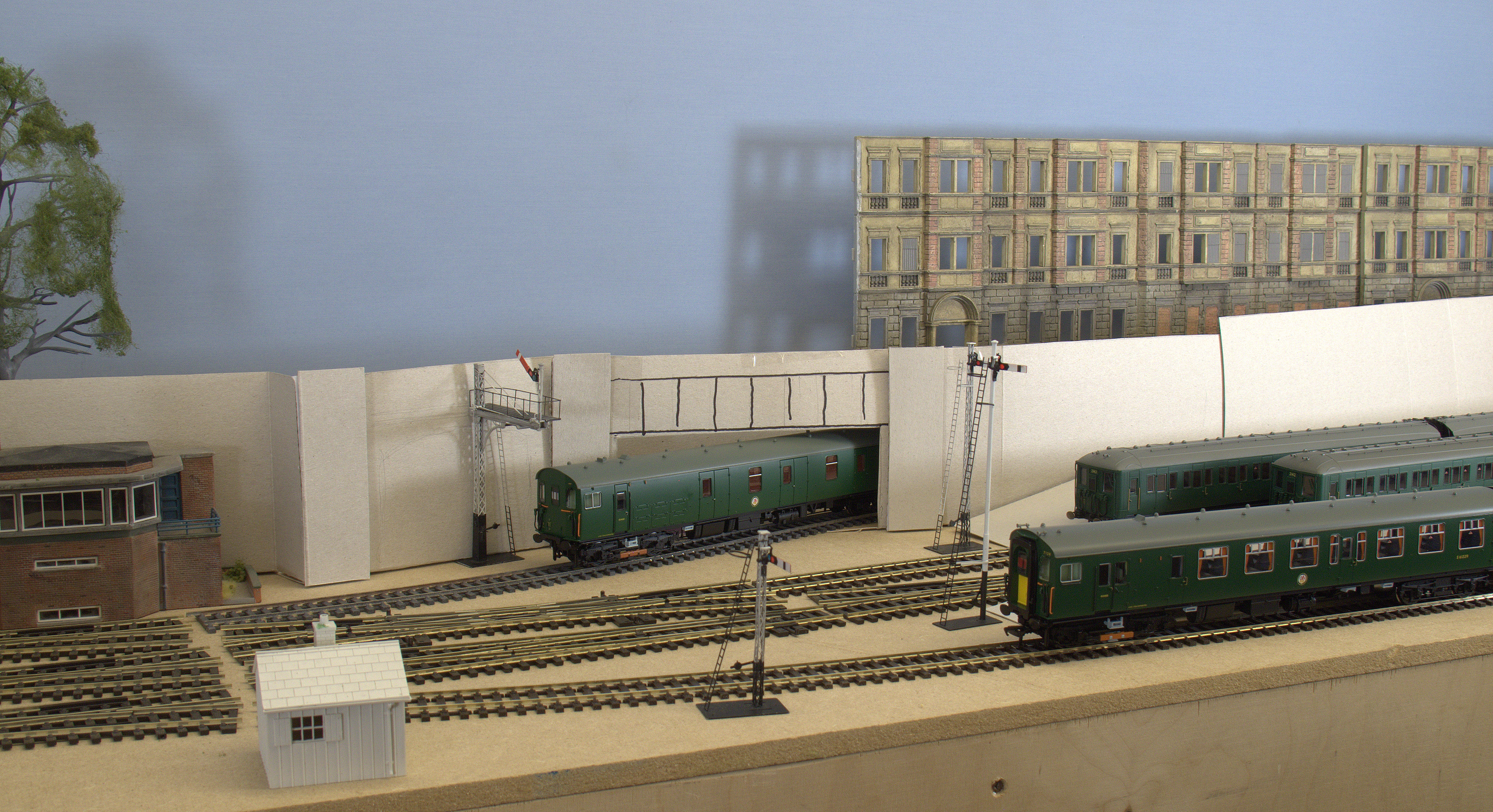
These are purely personal preferences, there’s nothing that prevents a builder either altering the height or operating position to suit their wishes. The entry to the layout is underneath an overbridge, this could be girder or brick construction, and forms the viewblock to the fiddle yard. It was common for there to be large advertising hordings in the vicinity of stations and to give some height to the bridge, we’ve shown a number of varying sizes. The signal box has a view in both directions of the station approaches and platforms, and is set back into the retaining wall keeping sightlines clear for the signalmen. Like the old ‘widened lines’ at Kings Cross there is a tunnel or cut and cover section which turns away from the platforms and dives under the roadway behind the retaining wall. On the model this is designed so that there is a kick back section behind the wall with a point that allows trains to reverse into the fiddle yard. Operationally this gives the impression the train has gone somewhere, as it doesn’t re-appear on the main board. These trains can be EMU’s, parcels or short transfer freights giving variety in the traffic flow. The inbound mainline has three variations, the widened line route, Platform 1 or Platform 2. Platform 1 is a straight turnround to depart on the main line back to London Bridge or South from Bermondsey. Arriving in Platform 2 the train has two reversal options, the main to London Bridge or the Greenwich branch. There is also the option to split a train here with one section returning to London Bridge and the other to Greenwich, or as two pairs to either route. Inbound from Greenwich, simple turnround branch trains can use Platform 3. If an onward journey to London Bridge is programmed then Platform 2 will accommodate that reversal, adding parcels stock to any of the routes will give more variations too.

Most of the movement and visual appeal occurs around the station throat one element of the design is to subtly draw the viewers attention to that area without overemphasising it. I had in my mind a picture of the end of Kings Cross Platform 1 whilst developing this. Without an overall roof at Kings Cross the backdrop would actually be three story commercial buildings separated from the station by the width of York Way. We’ve assumed the roadway is elevated and has an initial gentle gradient towards the station end of the layout. The retaining wall shows a very gradual height increase left to right around the station throat and is level once it reaches the first section of the platform. Our choice of backdrop here is like the real Kings Cross, and we’ve shown commercial buildings in the images. The other options include house backs like those on the approaches to Victoria or around Paddington, or warehouses and industrial premises.
At the station end the low overall roof marks the end of the layout. At the station building I’d like to emphasis the Southern location with an art deco style fascia leading to the short overall roof. The reason for the overall roof rather than station canopies is purely because it looks better. The roof is only the length of one coach or so, the viewer still being able to see most of the train thus giving the impression the platforms are longer than they are. The immediate foreground at the station building has a single story building extending into the layout, this hides the end of the layout and gives a visual cut off to trains that are at the station end of platform 3. The signalling for the layout is likely to be electric colour light. I’ve shown the appearance that semaphore signals would make, it’s also likely that there would be a gantry spanning the tracks outbound rather than the individual posts we’ve used for the mock up. The other big signature element of this layout would be the effective representation of the third rail current collection. Peco provide third rail components of the insulator pots and suitable rail, in their range that can be fixed to the streamline track system or to other brands and handbuilt track. The third rail, its cables,mixed with dummy point rodding has the potential to make a very visually interesting section of railway, that would be unusual and give an immediate visual link to the region and area of the country being portrayed.
Mock Up Procedure

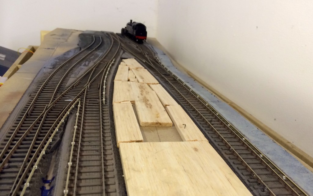
The first thing you need is clear space to work in. If you know the maximum footprint for your design it’s a good idea to mark out that area. One way of doing this is to use decorating lining wallpaper, it’s cheap and easily available and you can easily cut it to shape. For this project Paul and I had a baseboard chassis available from another project to the same footprint dimensions. The second thing we had was plenty of cardstock from cereal packets, this is easy to cut and form into shapes, and Paul Lunn is particularly good using this medium. The other thing to use is various boxes, model buildings you may already have, anything really that comes to hand that has the correct or approximate dimensional volume. If using card as Paul Lunn does, the appearance of the mock up is greatly enhanced if the colour of the card is the same of very similar shades. You will not we have used the unprinted side as the display, the printed sides are visually disruptive and it’s best not to have those on view. All you need is sharp scissors a straight ends and some selotape for this procedure. We make simple right angle brackets so the walls stand up vertical, and make simple strengthening beams for structures such as the road bridge fascia. You can them move and adjust the sections to bring the design to life. The station roof for example is card bent to an angle of about 45 degrees, nothing more complicated, yet they demonstrate the volume and shape of the station so simply.
We both had a pretty clear mental picture of what we wanted to end up with, I’d explained the ‘concept’, and shown Paul the projected track plan. Even at this stage the mock up may reveal a better track alignment or show something that’s not going to work, and this is part of the real value of this exercise, as well as it being really enjoyable.

For this plan the first part was to lay the track on the board so we both had a feel for the space available to us. We knew the retaining wall and low relief buildings would form the backdrop, so we were comfortable with the best viewing orientation of the layout. Again this mocking up exercise can show you a better viewpoint for a layout you may not have considered and its possible you could end up changing the entire viewing appearance of your model! Once the track is in place you get a feel for the space around the rails. You will immediately see how wide the platforms will be, the width of a road, how close buildings are to each other. These initial ‘screen grabs’ should give out warning signals, do you need to change building type or useage, should that be a different shape/style of house? Things like vehicle access, can you actually get a truck round that corner, or into that warehouse? If you are thinking maybe not, thats not gone well, at that point, that’s a real clue to change something. If you don’t, the finished layout will often look compromised. Addressing the problem will give you something that looks more plausible, even if in the real world it would still be flawed. These reality checks will help you think about the subsequent construction too, if I were to build this layout I already know how I will make the retaining wall work in the widened lines section, and how far I have to model the inside of the tunnel so you can’t see the train reversing.
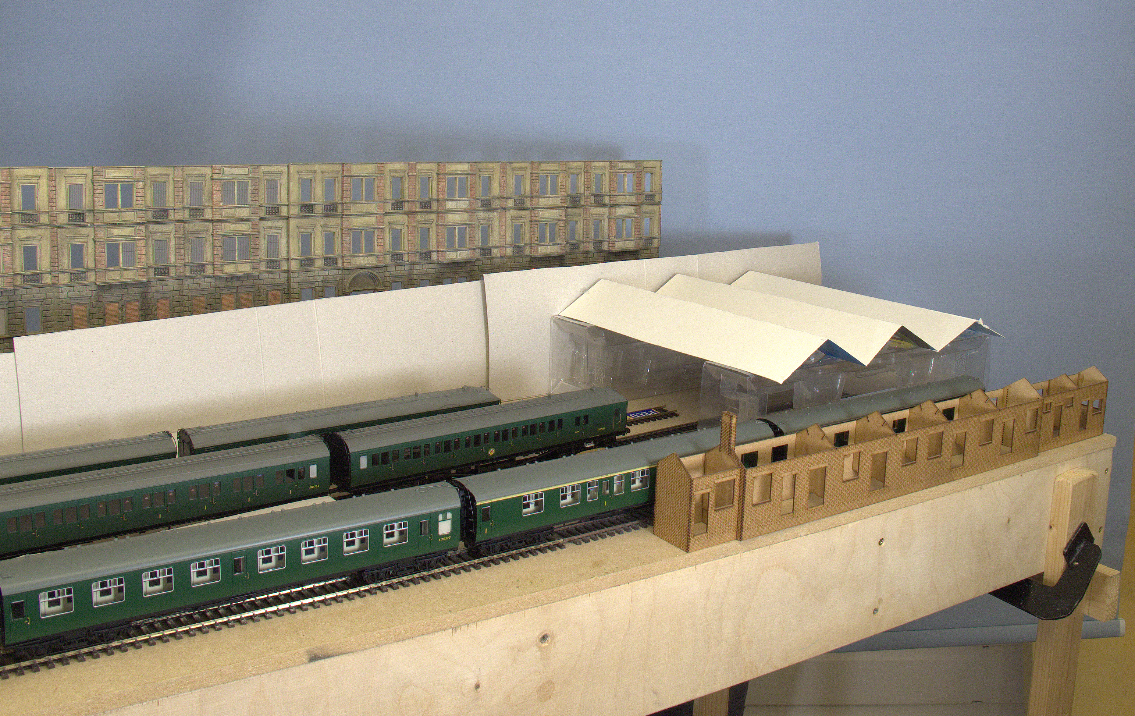
As you are building in full size consider keeping the components as they can act as a template when building the real model. Above, the buildings at the back give a sense of scale of the surrounding architecture. The design influenced by the buildings on the eastern side of York Way at Kings cross. The overall roof looks better in this format across the platforms opening the view. On this plan changes included the angle of the road bridge. Just moving it through an arc of 45 degrees or so gave us an optimum alignment, after that it was sorting the overall height out and adding the view blocking advertising hoardings. Having the commercial building low relief flats to hand helped us out, it gave us the immediate volume against the backdrop we wanted, and allowed us to look at the station itself. We modelled the platform ramps so we could get an appreciation of the station throat and estimated clearances, the rest of the platforms we left literally, to our imaginations. This is the beauty of this exercise, you don’t have to make everything, just the critical areas. We trialled to canopies for the platforms, initially we opted for a linear configuration, which looked ok, but had no real appeal to it. Paul then changed them to an overall pitched roof across the end of the platform. This immediately pulled the station end of the layout together, if you look at the images you can see we’ve used the packaging from the rolling stock as the supports for the roof, as they were the right height. The trains now looked more like they were entering a station of note, and the platforms look best with about one quarter covered by awnings. As this is a terminus the station building can be at the head of the platforms preferably at platform level, or there’s the option for higher street level with steps and lifts to platforms.
It can seem that this is a lot of effort to go to, and at face value it might appear that way. However, this only took Paul and myself about two and a half hours to do, so not a huge investment in time and extremely valuable in a planning sense. That two hours included discussion on what needed to be moved, what looks better, trying one or two different sizes of components and just doing the artist thing of standing back and looking at what we had made. We’ve got a very early indication of what the completed layout will look like at full size, with the relevant stock. Any missing elements are covered by the bit of our imagination that papers over the cracks, like the incomplete platforms! It has been an enjoyable exercise to see that such a simple plan gives plenty of movements, up to three trains moving simultaneously, and the potential to depict the flavour of intense suburban operations in inner London.
POINTWORK COMPONENT LIST AS DRAWN (Peco CD75 electrofrog)
1 x Wye point SLE-198
1 x Single Slip SLE-180
3 x Right Turnout SLE-188
2 x Left Turnout SLE-189

Minority is on my bucket list of layouts to build. Your version is I spring and we’ll thoughtthrough. Thank you for sharing this. Now I need to get enough money for some NSW double deck emu stock and make that happen.
Minories is on my bucket list for layout builds. Your planning is inspiring on a number of levels, not least is the short train lengths, which goes with my own thinking using Sydney, New South Wales EMU prototype. Thanks for sharing your design and the processes you’ve used to develop it. Highly instructional as always.
Thank you Andrew 🙂