

Many years back I settled on three link couplings for my rolling stock on the OO and EM layouts I’ve either made or been involved with. Their visual benefits are easy to see, but they do have a few practical drawbacks. On short stock they’ve worked well, however as stock length increases the potential for buffer lock increases too, even allowing for sprung buffers. Throw in a reverse curve and the chance of buffer lock increases again, and all the while these couplings require large radius curves, meaning that layout design has to take these couplings into account from the outset.

There are some similarities with Dinghams in this respect, ideally the layout design should take into account the couplings, and there are one or two catches in their set up and operation. So this is how the Dingham couplings are supplied, as a flat etch with soft iron wire for the electromagnet dropper. I’m using them on Shelfie2 the track is Peco Code 75 flatbottom rail as well as the new bullhead track too. Baseboard material is 9mm MDF and Woodland Scenics foam underlay between track and baseboard. Track is painted with acrylics and the ballast is a mix of DAS modelling clay, and Woodland Scenics ballasts.

I’d written I was experimenting with these couplings in an earlier post, and Mark Davy responded in the comments section. His comments on his experience matched mine and clearly he and Brian Lewis has overcome some of the issues I’d yet to find. Mark has kindly allowed me to use his comments which form the core of this post, the images are mine from those I’ve assembled, and I’ll add a few elements of my experience too. So without further ado, over to Mark whose comments and notes are in bold italics.
I’m interested to see that you are trying 4mm Dingham couplings for Shelfie2. Brian Lewis and I have spent the last couple of years fitting them to the stock for his ‘Tetbury’ layout (P4).
Since my fingers are a little younger than Brian’s, I’ve done most of the assembly and fitting. Over 100 vehicles later, I’ve learnt a lot of lessons; (and some interesting language !) You may find the following notes useful.
Assembly
Pivot point soldering for loops and latches
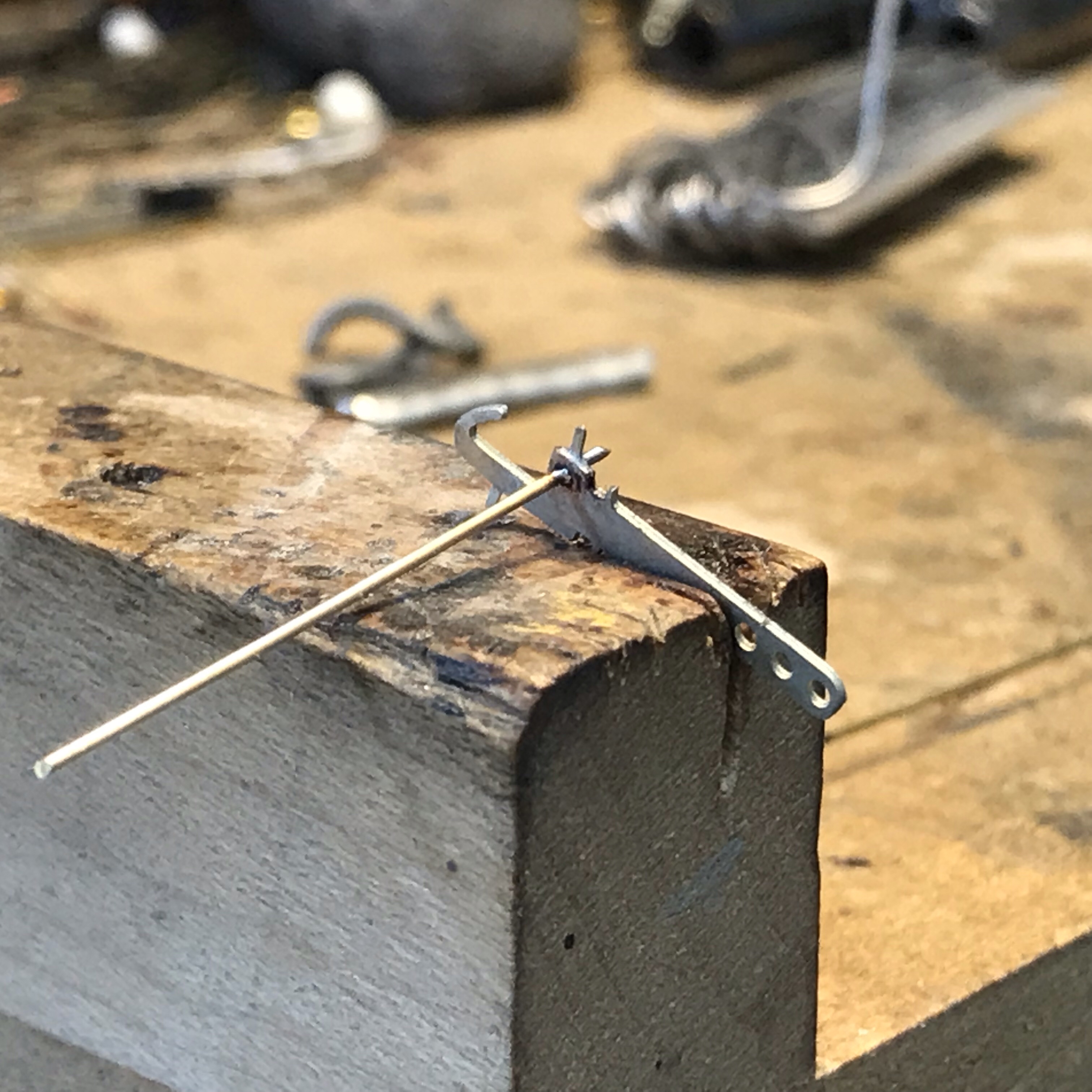
When soldering the pivot wire into the hook, I find the suggested wooden jig very useful. Tin the wire first (sparingly), push it through the hook into the jig, add flux and solder. Easier said than done as you don’t want too much or too little solder, and the pivot wire must be square to the hook. It usually takes me several attempts to get it right.
Pivot points completed, batch assembly makes sense!

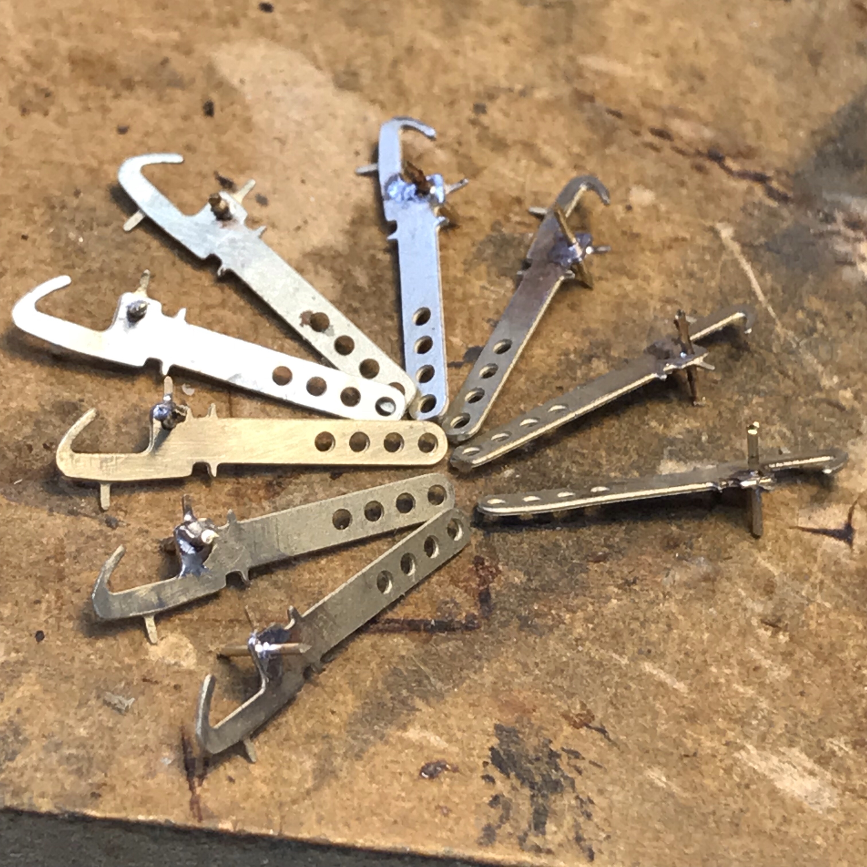
Pairings of loops and latches. The dropper tail can be adjusted to suit different chassis’.
When bending the tail of the loop downwards, it is essential that the bend is as close as possible to the pivot lugs, especially for 6mm buffer-length (unfitted) vehicles. I tend to make this bend (over the stock of an engineers square) before bending the pivot lugs upwards.
We also use the type 2 latch.

Type 1 Latches. The tail folds to roughly 70 degrees. Type 2 latches are U shaped.

Loops and latches ready for chemical blackening.
When finished, the latch and loop must move up and down freely. Once raised they are often reluctant to drop. Possible problems here are too much solder, the sides pinching the hook near the pivot or the tail rubbing on the hook.
I used a slightly different assembly method to Mark, I didn’t tin the pivot wire, I just tack soldered at the join to the hook, and then cleaned the joint afterwards.

Bachmann 03 with vertical dropper
The dropper tail should ideally bend under the buffer beam, however with the 03 Diesel shunter that wasn’t an option, so I have a vertical drop parallel to the buffer beam face. For the wire dropper I’ve used a thicker florists wire this can be glued rigid and doesn’t then get caught in any chassis detailing.

Type 2 Latch, soldered fillet
Type 2 loop, soldered fillet
The type 2 latch is a bit more challenging to make, but I found has better reliability, the latch is an etched ‘U’ shaped loop with the base of the U filled with solder
Fitting
Dinghams don’t work very well with sprung buffers – when propelling, the buffers compress and the coupling loop catches under the latch on the adjacent vehicle and so doesn’t uncouple. We now fix the buffers with a little Evo-Stik contact adhesive behind the headstocks/buffer beam. This can be removed fairly easily if required.
Buffers that project less than 6mm will need to be replaced with longer versions.
The instructions say that the end of the coupling hooks should be in line with the buffer faces. We’ve found that for reliable uncoupling the hook should be about 0.5mm behind the buffer faces. Otherwise when propelling the coupling loop catches under the latch on the adjacent vehicle and so doesn’t uncouple.
The instruction regarding the height of the hook at the headstock is good, but the coupling often droops while being glued into place, and it is the height of the front of the hook that is critical. I use a jig to support the end of the hook to hold it at the correct height while the glue sets. The critical dimension is 12.5mm from railhead to the bottom of the hook. Consistency is essential !
When first fitted the front of the loop often slopes from side to side, or is not quite at the correct height. Gentle tweaking should correct this.
I don’t recommend superglue when fitting the couplings – it tend to run around and glue the whole thing solid ! I use Evo-Stik contact adhesive, which can be removed fairly easily, but it takes some time to set and I’m sure it moves as it does. Five minute epoxy might be better.
It may not be possible to fit a hook with loop to some locos, because the chassis moulding obstructs the bent tail and magnetic dropper. The Hornby 14XX is an example. (The Airfix version is fine) Here we fitted a hook with latch at both ends and reserve the loco for auto-coaches with a hook with loop at both ends. (The Tetbury branch didn’t run auto-trains as such, but ran-round at the terminus)
You may find that vacuum and steam pipes sometimes prevent the loop from rising fully. Either bend the pipes to one side, or remove them !
Once the couplings are fitted, the magnetic dropper should be trimmed to just above rail head level – a full 1mm is not necessary.
When weathering rolling stock, keep the paint away from the couplings !
Mark and Brian’s experience matches mine almost perfectly. I’ve also found that free running stock can also give reliability problems. The sprung buffers and free running can allow stock to ‘bounce’ backwards and forwards, this can sometimes bounce past the hook and latch, so an uncoupled vehicle can re-couple again.
 Hornby 20T brake van with axle brake fitted, note brass wire bearing on the axle shaft.
To minimise this I put a brake on the axle of any particularly free running wagon. It’s nothing more than a piece of 0.5mm wire bearing on the wagon axle, this provides sufficient retardation for the wagons so they rarely leave a big enough gap for the loop to re-engage the opposing hook. This was a bit of a culture shock having previously ensured that all stock was running as freely as possible! For the fixing I have used low viscosity super glue, this gives a very quick and reliable fixing, which to date hasn’t caused any issues.
Operation
Initially we tried fixed permanent magnets with variable results, the main problem being trains parting unintentionally as they passed over the magnet.
We now use Gaugemaster (SEEP) EM1 electromagnets. These work very well on 24 volts DC. 12 volts didn’t have enough pull and AC makes the magnetic droppers jerk around, sometimes getting caught up under the vehicle.
When fitted, the top of the electromagnet pole piece should be level with or just above the sleeper tops, but not lower. The 4mm Dinghams are fiddly to make, but once correctly fitted are an ideal auto coupler for layouts where the stock does not need to be turned. The delayed uncoupling feature is invaluable.
Brian used the 7mm versions on his O gauge ‘Llaniog’ layout. Both on this and his previous ‘Chagford’ layout (P4), he experimented with other auto couplers – Sprat and Winkle, DG, Winterley and AJs. All had their good and bad points. Some were obtrusive, some required an unprototypical shuffle in order to uncouple. Others did not take kindly to being transported or being subject to rough shunts and so needed constant tweaking. Opinions are subjective, but on balance he feels that Dingham couplings score highest in terms of all round reliability. Our couplings are not 100% reliable yet – but we’re getting there!
 Magnet location hidden beneath darker green foliage.
Like Mark and Brian I’m very pleased with the Dinghams. They do take a bit of effort in their manufacture and fitting. I’ve been very fortunate with Richard Chapman sending me some ready built couplings which worked superbly and helped me get my head around the construction and fitting of them. I’ve used a 15V DC source for my electromagnets, a Scalextric power supply which gives a smooth and efficient operation with a high 90% reliability. I’ve been using switchgear made from press to make, non latching switches which have not been reliable, the contacts have needed cleaning on a few of them. The next step is to build a dedicated switch box with better quality switches from RS components.
If you’re interested in seeing these ‘at work’ Shelfie 2 will be at the Define Modellers show on the 12th January at Risley, Derbyshire. Define 2019
Once I’d become accustomed to using three link couplings over many years, I didn’t think I’d be so taken by these couplings. All coupling systems have their advantages and disadvantages, these appeal as they are completely hands free and once blackened very discreet in their appearance. One disadvantage is they are ‘handed’ so all stock has to be run facing the same way, so the original idea for a turntable fiddle yard isn’t practical. I’m not sure I’ll use them across other projects at the moment, the uncoupling does require straight or almost straight track, and coupling up on tighter curves occasionally means the loop misses the hook, sliding alongside the latch hook.

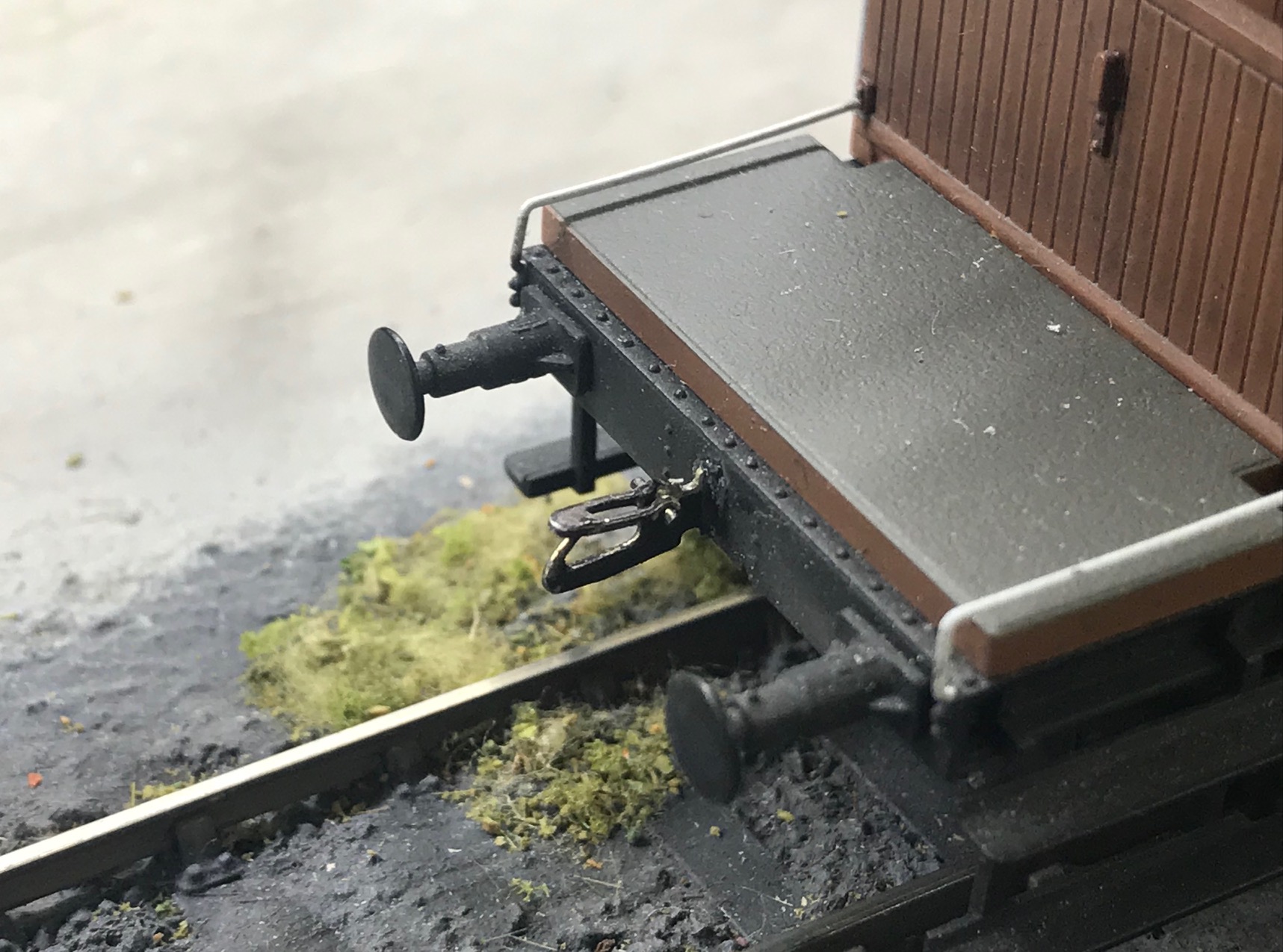
Bachmann 08 fitted with Dingham autocouplings
Locomotive control has to be excellent to allow the couplings to operate reliably, I chose the Bachmann 08, 03, 25, and 57xx pannier for my test fleet, knowing they would have the slow speed consistency required. The real appeal of Dinghams for me is that Shelfie2 is now completely hands free operation. With hand controllers for points and couplings, the operator can walk around the front of the layout enjoying the different views, or at an exhibition, sit out of the way of the viewers, yet still be able to see and operate the layout in effect remotely. If you’re looking for an uncoupling system that is relatively discreet, can be worked hands free and don’t mind a bit of effort in setting up the system, for 4mm scale Dingham are well worth investigating.

This is a very interesting blog. I’ve never heard of these particular couplings before but some of the challenges of operating with Sprat and Winkle couplings are very similar, including free running wagons being a problem (I have a blog in the works on this too). I had resolved this to an extent by weighing down each wagon, but adding a brake is a very good idea which I might try, so thanks for that.
You’re welcome, I looked at the S&W too but felt they were too obtrusive visually, but I’ve heard good reports on their effectiveness.
The S&W’s are nice and simple on locos as they just require a hoop bar. The hooks are a bit bigger than your ones but you can get a smaller scale version which is less intrusive. I have bought some of these to test. Like the couplings you have, there are a few things I am starting to change on the S&W’s. One being to have only one hook at one end of each truck as it limits coupling lock-ups on short radius points.
A benefit of the single-direction running is you only have to letter one side of your wagons!
It’s just a delaying tactic, you still have to do the other side when you sell your stuff! HNY Rene! 🙂
Well, as we have all shown models that still smelled of paint, and I have exhibited many with lettering on one side only, I think any delay we can get is a win! Happy New Year